I'm very excited to bring you this page. This work comes from a collaboration with ChenYang Technologies (http://www.chenyang.de/), a company based in Germany that produces and researches on Hall sensors and magnets.
Click to jump to the desired paragraph:

Quick links:
• Arduino code for reading CYSJ902 Hall sensor connected to ADS1115 external ADC board;
• Arduino code for reading Hall sensor and moving a servo-based linear actuator;
• Octave/MATLAB script for computing 2D fields.
Intro: sensors for measuring strong magnetic fields
So, a couple of months ago, I started experimenting with plasmas and magnets, with the final aim of eventually building a plasma thruster. You need good magnets for that. Simple ferrite magnets could work OK and will deflect electrons, but neodymium magnets are much stronger, and occupy much less space.So, here came the need to measure these magnetic fields, and the most simple way to do that is using a Hall sensor. To my surprise, I couldn't find on ebay (nor in many other retailers of electronic components) any Hall sensor with enough Full Scale to measure neodymium magnets! Most sensors available online have a FS of about 64 milliTesla (640 Gauss), which is not nearly enough for our purposes.
While searching for a good alternative, I came across the website of ChenYang Technologies. They were offering a variety of Hall sensors, large ones, small ones, and in the catalogue they had exactly what I was looking for: 3 Tesla Full Scale Hall sensors! Moreover, the cost was just a couple of Euros each.
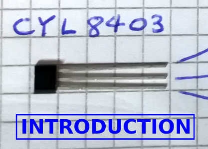
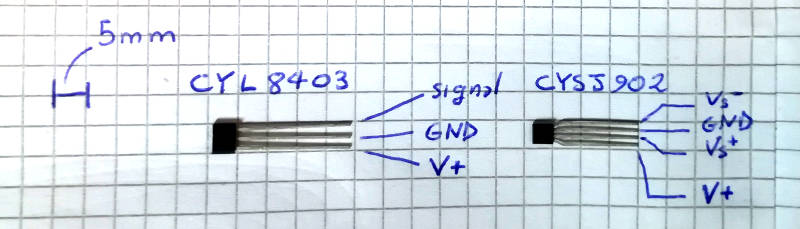
I got in contact with them, and they offered to send me a few of their sensors to review on my website. Here's a PIC of the sensors with the pinout. They are a CYL8403 (full scale 640 Gauss) and the CYSJ902 (full scale 3 Tesla).
So, in this page I'll show you guys how you can use these sensors. All in all, since they are so simple to use, I'll spend most of the time showing you some cool plots! By the way, if you want to see their magnets in use, check out this page.
OK, let's start.
Electrical connections: Arduino schematic for the CYL8403 and the CYSJ902 sensors
Reading these sensors is super simple. The CYL8403 is a linear sensor: you just apply a voltage and it gives an output voltage that you map linearly to the magnetic field (see the plot in the datasheet). The simplest thing that you can do is connecting it as follows:
The Arduino board is connected directly to the USB of your computer here. In the code, all you have to do is reading the voltage applied on the pin A0, convert it to Gauss (following the calibration curve in the datasheet) and print it in the serial monitor. Super simple, and this works fine for not demanding measurements.
The only drawback is the rather low resolution of Arduino's internal ADC, that is 10 bits (aka the reading is composed by 2^10 = 1024 levels). This limits the resolution to about 4.8 mV. For the CYL8403 the Full Scale is 640 Gauss, so that a direct connection to Arduino would provide a granularity in the reading of 640/1024 = 0.62 Gauss. You cannot read lower than that with this simple connection.
Fortunately, there's something that we can do: we can employ an external ADC module! The ADS1115 external ADC board for example provides a 16 bit resolution (2^16 = 65536 levels), that for the CYL8403 means 9.7 mGauss. Around 100 times better! Moreover, in case your signal is very weak, the ADS1115 allows to set a gain, allowing to increase the accuracy further.
I'll how to connect this board in a moment. Before that, let me introduce the other Hall sensor that I'm using, the CYSJ902. This sensor has a much larger Full Scale of about 3 Tesla. This makes it ideal for measuring the field of Neodymium magnets, that on the surface is often in the order of some kGauss (1kGauss = 0.1 Tesla). Of course, farther from the magnet the field drops quickly, and here comes the high resolution of the ADS1115 board!
So, here's how you connect the board. The ADS1115 communicates to Arduino via I2C, so you need to connect 5V, GND, SDA and SCL. On Arduino Nano, SDA and SCL are respectively pins A4 and A5.
Then, you connect the CYSJ902 Hall sensor to the ADS1115 board. The CYSJ902 has a differential output, meaning that the output is given on two pins, the "+" and the "-" of the signal. These are well suited to be connected to a differential amplifier (such as the ADS1115 itself). There are two ways for feeding the CYSJ902: you can use a current generator or a fixed voltage. The latter is probably the fastest if you don't have much equipment at home. In the datasheet I found a calibration curve (converting output voltage to magnetic field intensity) for an applied voltage of 6 V. So, here's the full schematic and the arduino script:

  #include <Adafruit_ADS1015.h>

  Adafruit_ADS1115 ads1115; // construct an ads1115 object at default address 0x48

  void setup() {
    Serial.begin(9600);        // Set baud rate for serial monitor
    ads1115.begin();           // Initialize ads1115
    ads1115.setGain(GAIN_ONE); // Set gain to 1. Other options are possible.
  }

  void loop() {

    // Read sensors and average values
    int16_t adc0;
    float adc0_ave = 0.0;

    int NAVE = 20; // Average on this many readings
    for(int i = 0; i<NAVE; ++i){
      adc0 = ads1115.readADC_Differential_0_1();
      adc0_ave += (1.0*adc0)/(1.0*NAVE); // Compute double (note: int / NAVE would round off! Multiply by 1.0 as to convert to double!)
    }

    // Convert adc signal to mV
    float mV = adc0_ave*4.096/32768*1000; // valid for gain 1

    Serial.print(mV);
    Serial.print(' ');

    delay(10);
  }
Needless to say, instead of the CYSJ902, you can connect the CYL8403 sensor to the ADS1115 if you wish! In this case, since the CYL8402 only has a single output (referenced to ground) you will only use one pin of the ADS1115 board, say A0. Then, you'll perform a "single-ended" reading.
Automatic measurements
What if you want to get some spatially resolved measurement? I mean: what if you want to plot the magnetic field along one axis? In this page, I had measured manually, point by point, the magnetic field generated by a couple of coils. It takes a bit of time to sample just a handful of points.If you have a 3D printer, you can easily print a linear actuator that will scan one space dimension for you. And if you glue a Hall sensor on its tip, you can make beautiful plots of the magnetic field.
Here's a video of the system in operation, and a pic of the complete setup mounted on a breadboard.
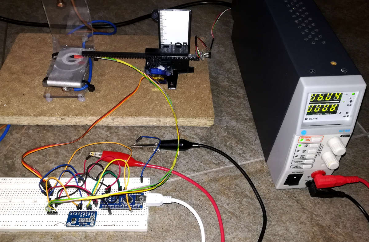
The linear actuator in the video is run by a cheap arduino servo. Here's an Arduino code that moves the servo on 50 steps, and reads the magnetic field at each step.
First application: magnetic field inside a microwave oven magnetron
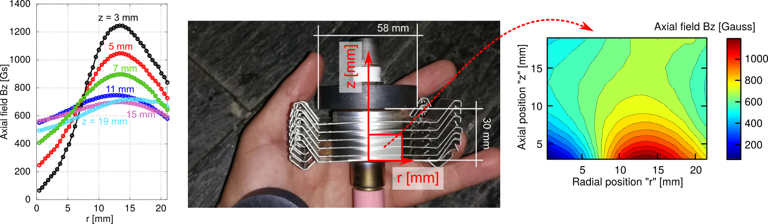
As a first application, let us measure the magnetic field inside the magnetron of a microwave oven. As you probably know, magnetron devices generate a cloud of electrons and spin them by creating a uniform magnetic field. This field is generated with two magnetic rings, as you can see from the picture below, where the bottom magnet was removed and I'm holding it in the palm of my hand. The field is quite strong, so that you should use the sensor with larger full scale to read it.So, to measure the field I have removed the magnets and created a small structure to keep them in their original configuration (roughly 3 cm) apart. And here are the results of some measurements, plotted with Octave.
As you can see from the plot, the magnetic field is far from being uniform, except in the centerline (around z = 15 mm), where it averages around 650 Gauss.
Attention! Opening a microwave oven is an extremely dangerous activity and involves deadly high voltage, even when the oven is unplugged! Don't do this! We are not liable for any damage you may do on anyone or anything.
Reconstructing 2D fields by using some math
I want to show you guys a cool feature here. Imagine that you want to measure and plot magnetic field lines. Since the magnetic field is a vector, you'll need to measure two components on a plane, and then plot the magnetic field lines by following these firections.So, you need to perform two sets of measurements, in the same space locations, but turning the Hall sensor 90 degrees. Or, you'd need to glue two Hall sensors together (again, at 90 degrees from each other, to sense the two different components) and scan the field at different locations.
Right?
Right... But I want to show you a cool trick here. Remember the basic laws of magnetostatics: Faraday's law and the divergence-free nature of the magnetic field? In absence of currents, they state:

These equations are telling us that the components of the magnetic field Bx, By and Bz are connected to each other. Consider now our special case: we have measured the Bz component of the magnetic field on a plane passing by the center of the magnets, and the configuration is symmetric around the "z" axis, right?
Right! So, we know that on such plane, the magnetic field configuration is also symmetric around "z", and therefore the azimuthal component of the magnetic field is "BΘ = 0".
So, in our case the "div(B) = 0" equation becomes:

Do you see where I'm going? We have measured Bz on a plane, so we know its derivatives... and we can integrate the equation with respect to the radial position "r" and we can retrieve Br.

What about Br0 you said? Again, thanks to symmetry, Br(r = 0) = 0.
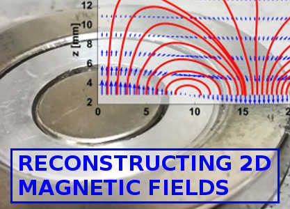
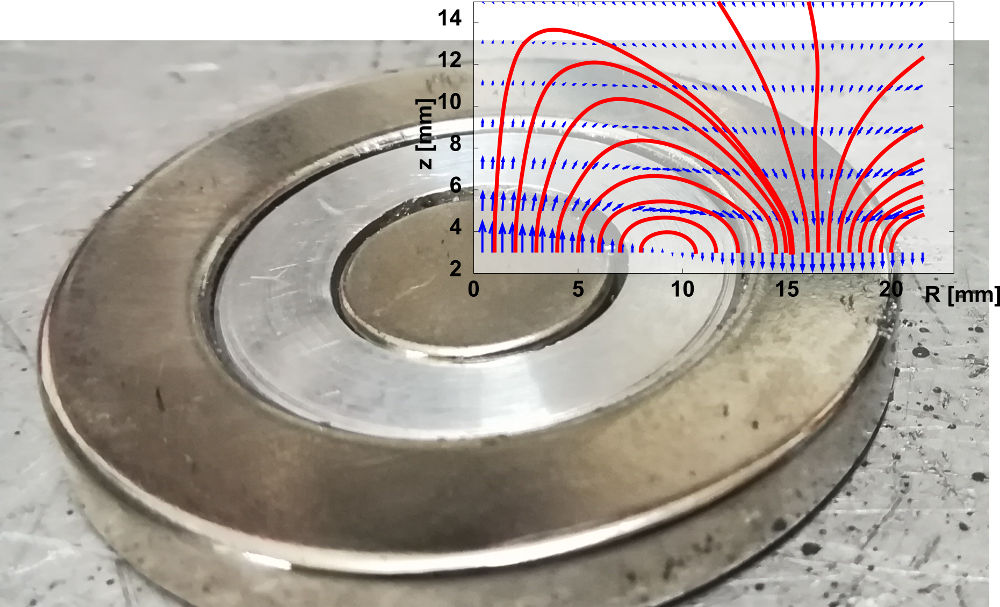
So we are good! HERE'S A LITTLE MATLAB/OCTAVE SCRIPT that does this trick and plots a 2D magnetic field. Here is the magnetic field, computed from this script, from the planar magnetron configuration discussed in this page. I've superimposed the magnetic field lines on the magnet, so that you can see what's going on. You may be a bit surprized by the shape of the field, but keep in mind that the internal disk magnet is much smaller than the outer ring magnet. Therefore, there are a number of magnetic field lines that originate from the outer ring magnet that do not reach the inner one!
Acknowledgements
Thanks to ChenYang for providing the Hall sensors used in this work.And thanks to my brother Riccardo for collaborating in building the system. If you don't know this yet, check out his cool website!
Cheers,
Stefano