Planar magnetron experiment
Cremona, September 2020.
Back to the home page.
Hi folks,
this page describes a very fun topic:
plasma discharges and magnetic fields.
In particular, today we investigate a planar magnetron configuration.
Theory
Magnetrons are devices that confine electrons and make them spin around, creating a sort of toroidal region with a more concentrated plasma.
They are designed as to create a crossed electric and magnetic fields configuration.
The magnetic field is usually obtained by using permanent magnets, while the electric field is creating with the use of a high voltage source.
The configuration is shown in the figure:
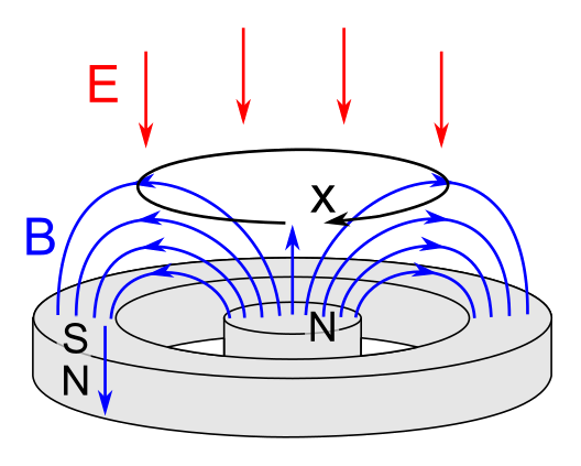
So, one puts a positive electrode (say, a few kV) on the top (not shown in the picture) and a negative electrode at the bottom, just on the
top of the magnets.
The device is then operated at a low pressure.
Not too low as to have no more atoms in the chamber, but rather low.
Ok, so, what happens is that a pretty diffuse plasma discharge (a glow discharge) ignites between the electrodes.
Electrons will ionize the background gas, producing ions and more electrons.
The electrons will be attracted towards the positive electrode and ions towards the bottom electrode.
Now, the particular feature of magnetron discharges is that electrons are strongly influenced by the
magnetic field.
In particular, they will be trapped by magnetic field lines.
And if you do the math, you'll see that the particular crossed configuration of electric and magnetic fields
at roughly 90 degrees will make electrons spin around, as indicated by the arrow in the plot.
This configuration creates a region of denser plasma near the magnets, which is shaped by the magnetic field itself.
In other words: a beautiful plasma donut!
Quite often this process is used for sputtering a metal on a substrate, that is, the electrode close to the magnets is negative as
to attract the ions, that hit it and sputter atoms from the electrode, and they then deposit around on the chamber and on the
substrate.
Industrial magnetron sputtering devices often operate at a quite low bakgroud pressure, say 1 Pascal (approximately 10 mTorr).
If you know about the Paschen law, you'd know that it is quite difficult to maintain a discharge in this regime,
since the mean free path of electrons is large and electrons will leave the domain even before ionizing a gas atom, right?
Right.
But recall that we have a magnetic field!
Electrons will be trapped by the magnetic field, that will strongly increase their residence time, increasing A LOT their
collision probability!
So much for the theory.
Let's build a magnetron.
A simple experimental setup
So, we need to create a magnetic field like the one in the previous figure.
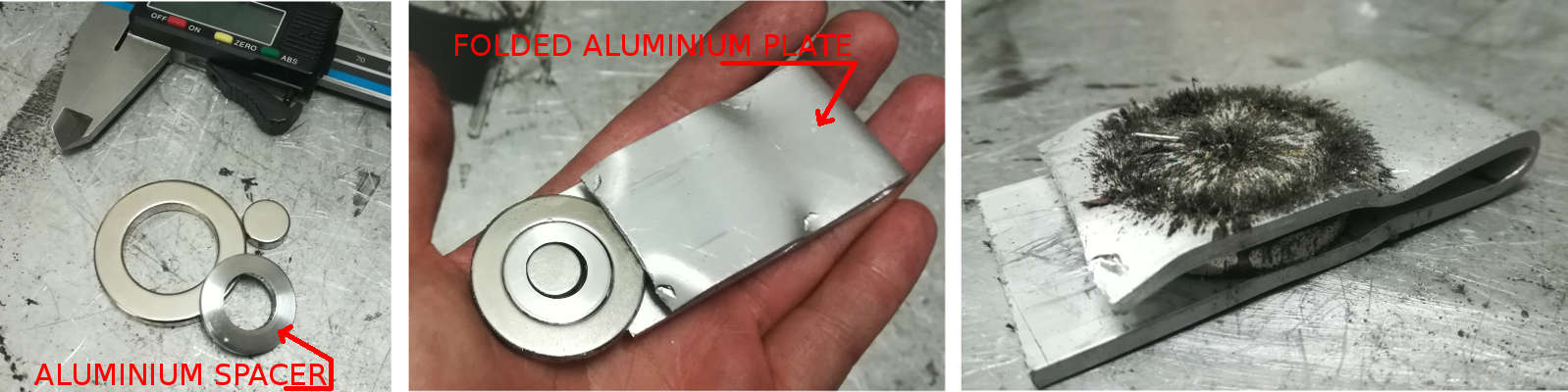
I got from ebay a ring and a disk neodymium magnets, and machined a small aluminum spacer to keep the internal magnet in place.
Pay attention to the direction at which you put the two magnets, or it won't work.
To keep them in place, I folded an aluminum plate, that will also serve as a cathode.
Note that using a ferromagnetic cathode may be a problem, since this would bend magnetic field lines!
If you'd employ a thick ferromagnetic plate as a cathods, magnetic field lines leaving one magnet would curve into the ferromagnet and re-enter the other magnet.
There will be no field out of the catode, and therefore no electrons confinement.
So, use a non-ferromagnetic cathode.
If you toss some iron filing on it, you can see quite clearly the magnetic field structure!
I took some time to measure the magnetic field using a linear Hall sensor, a CYL8403 by ChenYang (http://www.chenyang.de/).
They cost just a couple of Euros and are super simple to read by Arduino or with a voltmeter.
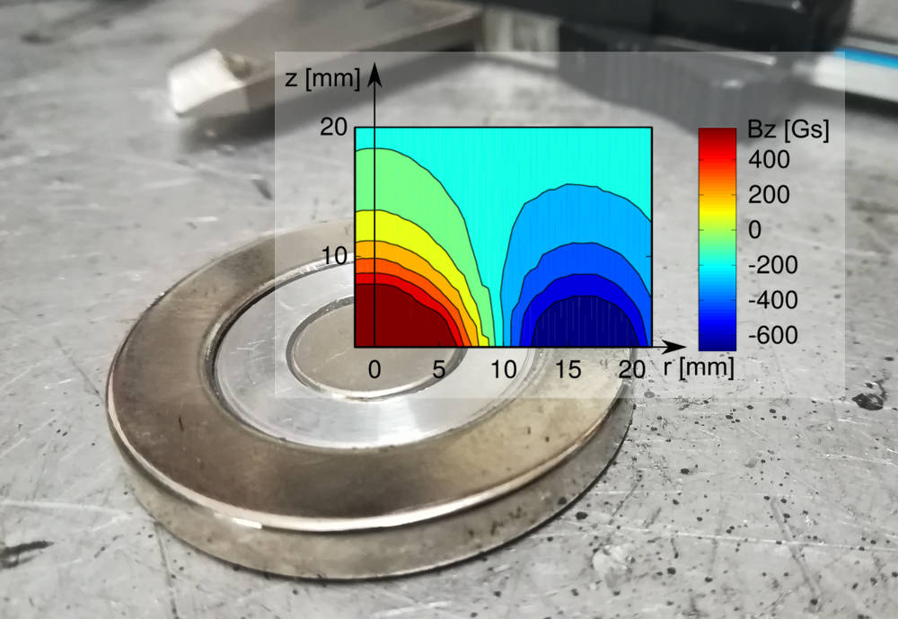
Here's a plot of the Bz field, superimposed with the magnet.
In proximity to the magnet, the field goes beyond the full scale of the sensor, that saturates.
You'll need a sensor with a higher full scale for measuring close to that region.
Note that in the image I'm showing the axial component of the magnetic field only, Bz!
If you want to plot the field lines, you'll also need the radial component.
To know more about this, and about how you can measure a magnetic field,
you can check out this page,
where: (1) I'll describe a simple setup to measure the magnetic field, (2) I'll test the CYL8403 and also another sensor with a much higher full scale,
(3) I'll compute 2D plots of the magnetic field by mixing some measurements with the Faraday's law!
Really, check it out, it's cool!
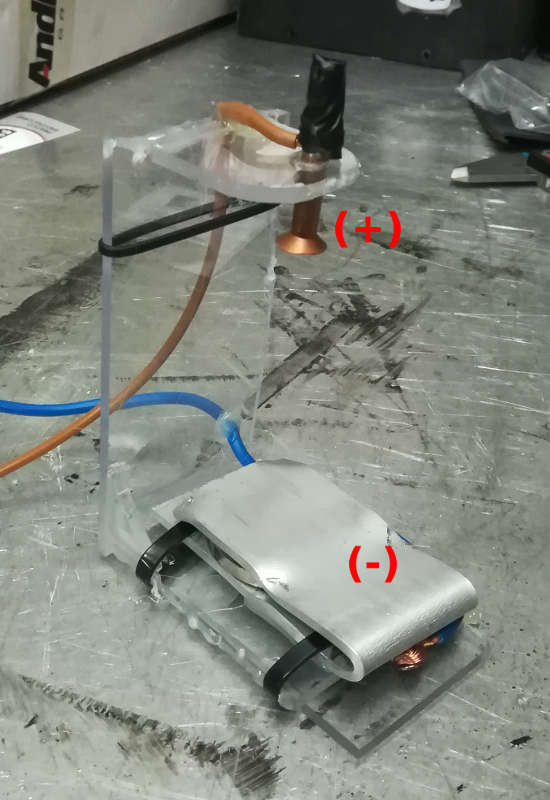
So, here's the picture.
Also, at this point we just need an anode and some stand to keep everything in place.
Power supply
For demonstration purposes, you can use any power supply that you like here, as long as they can ignite the discharge.
For tabletop dimensions, some kV will suffice.
ALERT: PLAYING WITH MOTs IS DANGEROUS! YOU MAY DIE, AND VERY BADLY.
In this experiment I'm using a MOT power supply with some current limiting, and rectified output.
The output is rectified by using 4 scavenged diodes, that always come with the MOT.
I connected them in a full-wave rectifier configuration and embedded in epoxy.
MOTs can be plugged directly to the plug voltage of 220V only for a small amount of time.
They are not designed to do that, and they overheat a lot.
Plus, they output a large current from the secondary, which is pretty scary.
Pretty much like Voldemort's "avada kedavra".
What you can do is limiting their current by placing some load in series with the secondary.
For reference, I'm using a 700 W heating resistor, from an old grill.
Of course, 700 W are dissipated when the heating element is directly connected to 220V, which is not the case.
So, the element won't heat up much, and it will mostly act as a current limiter for the MOT, without impairing the output
voltage significantly.
ONCE MORE, SERIOUSLY, MOTs ARE DEADLY. IF THERE IS SOMETHING DANGEROUS IN LIFE, IT IS A MOT. NO KIDDING.
Switch on the plasma
Ok, ready for switching on the plasma!
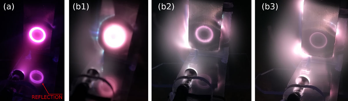
I'm operating the device at a somewhat high pressure here, around 150 Pascal in air (a bit above 1 Torr).
And as you can see from the picture, there is definitely a cool torus of plasma, shaped by the magnetic field!
In the next figure you can see the magnetron device working with the current limited MOT figure-(a),
then out of curiosity I tried to remove the current limiting element and operated the MOT at full power (Figure-(b1),(b2),(b3)).
At the beginning it was kind of fancy.
Very bright (sorry, in (b1) I couldn't focus the camera!) and it was showing some sort of low frequency oscillation, in the Hz range.
They were quite visible at naked eye, so it's quite likely that they were
linked to the unleveled pulses coming from the rectifier, at 100 Hz (2 times 50 Hz for the full wave rectifier).
Also, the pulses were rotating.
When operating at full power, the surface was glittering.
Probably sputtering in action?
Anyway, this didn't last long, and soon the electrons confinement broke-up, the plasma started to detach from the magnetic field,
rotating around (in the ExB direction I suppose!), it expanded all over and then I just switched it off before damaging it.
As it turned out when I opened up the chamber, the cathode had heated up quite a bit, and the magnets were also pretty warm.
Neodymium magnets are known to have a quite steep magnetization loss with temperature, so it's likely that as the cathode
(and the magnets) warmed up, the magnetic field decreased to a point where most electrons could easily escape.
Sputtering and oscillations
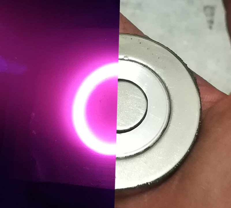
You may wonder if the plasma is actually located as described in the
previous "Theory" section.
So, here's a comparative view of the plasma and the magnets.
The image is a bit slant, sorry about that.
In any case, you can clearly see that the plasma is roughly corresponding
with the spacer aluminium ring, where the magnetic field is perpendicular to the plate.
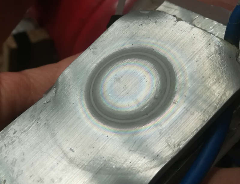
And in case you are wondering if any sputtering happend at all, you bet it!
The surface was clearly eroded (I believe this mostly happened when operating the MOT at full power), and
you can also see a rainbow around it, that could probably be linked to the thickness of the aluminum oxide layer.
Cheers,
Stefano
Where to go now?
Check out the VACUUM DIARIES page
,
...or you can visit the EXPERIMENTATION PAGE,
or you can GO BACK TO THE HOME PAGE,