Cremona, ??? ???.
Back to the home page.
In collaboration with ChenYang Technologies
THIS PAGE IS A WORK IN PROGRESS!
Hi folks,
in this page, I'm showing you a JxB accelerator.
You might remember some previous testing, done on a very simple configuration, where the whole structure was made of
hot-glued plexiglass and the electrodes were made of aluminum tape.
Check out that page
for an introduction to the topic.
That was a good concept, but as soon as I plugged a stronger power supply, the electrodes destroyed in a fraction of a second.
So here we go with a better version, the JxB Accelerator Mark I.
It will be made totally out of plastic to speed up the prototiping, so you can guess that it's not for prolonged or high power usage!
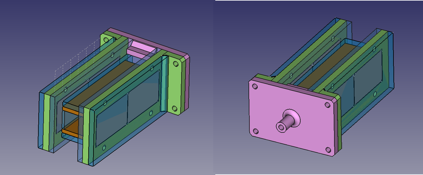
Here is a preliminary CAD model (did you know FreeCAD for Linux? Check it out!).
As you'll see, some modifications were included while building it.
The green parts hold the magnets and the pink part is the gas inlet.
The copper parts are (guess what) the two parallel electrodes, and the transparent parts are just insulation (plexiglass or polycarbonate).
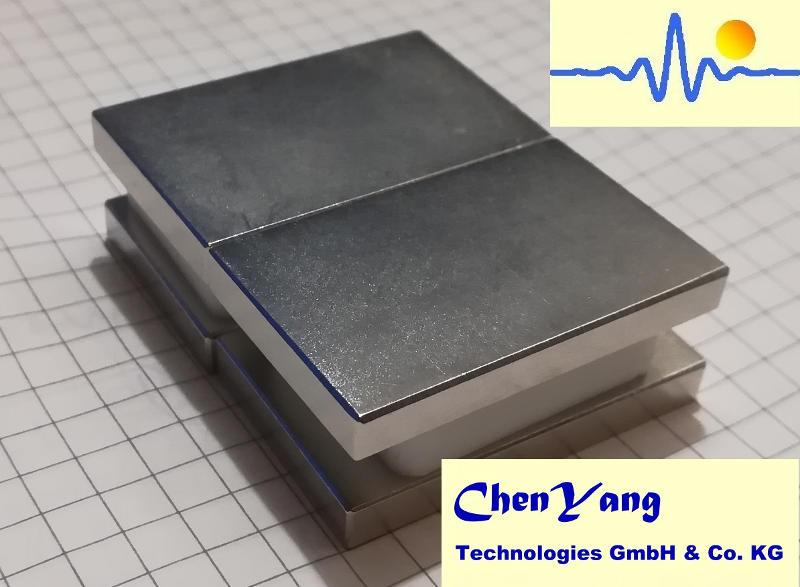
The core of this accelerator are the magnets, that I got from ChenYang Technologies.
I got in contact with these guys a while ago for a partnership with BoccelliEngineering, and they have been amazing all the way.
They have a broad range of neodymium and samarium-cobalt magnets.
For this project, I'm using four 40x25x5 mm neodymium magnets, that you can see in the figure.
They generate a pretty strong magnetic field!
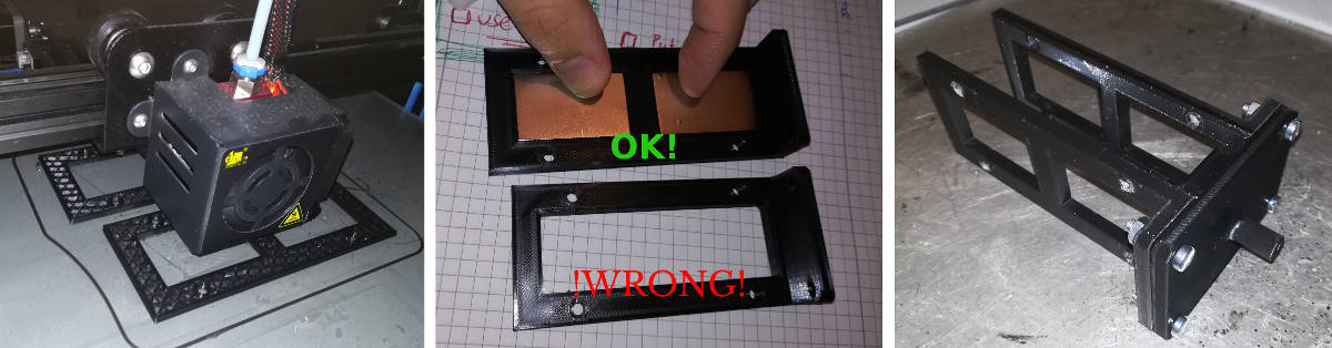
In the accelerator, I keep the magnets in place with a 3D printed a magnet holder, that you can see in the figure.
It's basically a rectangle with a couple of slots, one for each magnet.
The magnets are then sandwitched in with two plexiglass layers.
You may have noticed in the CAD image above that I originally had envisioned a single slot.
Rookie mistake!
The magnets need to be oriented as to create a uniform magnetic field in the channel.
With this orientation, two magnets will not stay side by side, but will repel them.
And I told you they are strong, right?
So I had to modify the design as to keep a 10 mm space between them.
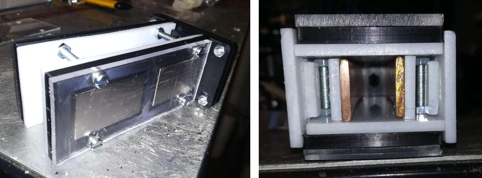
Here's the assembled structure.
In the previous simple attempts of a JxB channel I had used simple aluminum tape for the electrodes.
They were good for my flyback transformer, but didn't last more than a couple seconds when I plugged the MOT power supply.
For this accelerator I'm using two copper plates, 20 x 3 mm each.
Pretty sturdy.
Designing a cute assembly for the electrodes is less trivial than it may appear.
You want the discharge to be localized in the channel, so you don't want them to touch any bolts.
Also, you don't want the magnets to touch the discharge, and you don't want turrent passing through it!
That's because if you heat up neodymium magnets, the magnetic field will drop fast.
Check out this page about a magnetron plasma to see the magnets decreasing their strenghts.
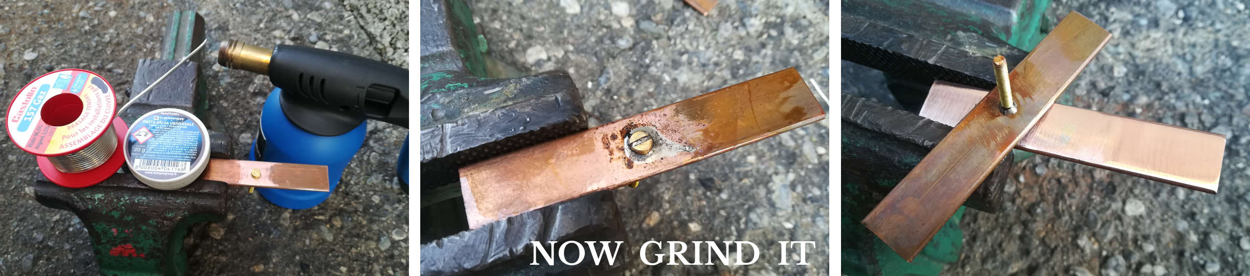
So, the strategy that I used was drilling the electrodes, passing a brass screw trough them and soldering it in place.
Then, I'd drill a hole in the plastic insulation and access the electrodes from outside.
I'm using Castolin to solder them.
To get a good resul, you should drill a hole of the exact size of the screw, then you put some solder flux for deoxidising the surface, insert the screw, heat up with a
flame torch and just put some solder around it.
Capillarity will do the rest and will get all through the hole.
Finally, you can just grind away the screw head from the electrode surface.
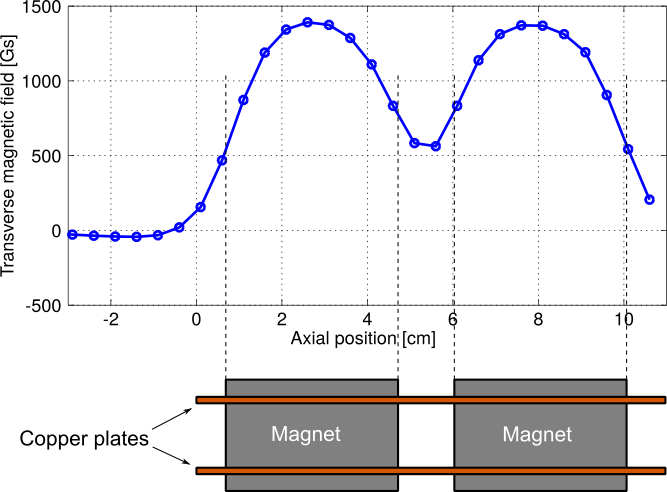
Here's a plot of the magnetic field between the two magnets, roughly at the channel centerline.
The measurements are taken with ChenYang's CYL8403 Hall Effect sensor that has a 3 Tesla full scale
(check out this page
for a detailed description and some arduino and Octave/Matlab scripts).
Apparently, the hole between the two magnets has quite a strong effect in the magnetic field profile.
Lessons learned:
Two strong magnets won't stay side by side, unless strongly constrained;
A long magnet may be more fragile, but two smaller magnets will create a much less uniform magnetic field.
Of course, all this could have been easily found by proper simulation.
Preliminary plasma analysis
From the magnetic field, we can compute important quantities such as the Larmor radius.
Assume the ions have a temperature in the order of 500-1000 K.
The thermal velocity is in the range 600-850 m/s for air molecules.
Take a magnetic field of B = 0.1 Tesla, we obtain an ion Larmor radius in the range rL = 1.8-2.5 mm.
This is for ions! That's quite magnetized, ok?
Here are a couple of videos of the device, run while changing the mass flow rate from approx 0 to approx 1 SLM (standard liters per minute):
LEFT: using a MOT power supply (limited by a series resistive load) and
RIGHT: using a flyback power supply with ZVS driver.
Different regimes are quite visible in the second video: when I switch on the flyback power supply (about 30 kV, with a few mA of current)
the mass flow controller is off, and you see mostly excitation and further emission from the background gas, that is at 1 Pascal roughly (7.5mTorr), and slightly
more inside the JxB channel, due to some small nonzero mass flow rate.
As I increase the mass flow rate, the colors change quite a lot, as different excitation mechanisms appear.
The gas is simply ambient air in these tests.