I used a three way fitting (for high pressure gas) and connected a baratron to check which pressure I could obtain (check out this page for the details on the baratron reading).
If you look closely in the figure, you will see a tiny three-way joint, with a nice red tap. Before that, I used a gas-grade T fitting and tap (left picture, below). This was apparently leaking quite a bit, because pressure would hardly go below 100-200 Pa. Moving to more proper fittings (picture, right), for fridge-grade vacuum (at least, that's what they say on ebay..) improved things. The system is not that bad: the baratron was indicating something around 13 Pa after some time of running! I think some leakage is still due to the red tap, and probably where the hose is connected to the pump.
Level up: larger vessel
My current attempt is replicating this pressure on a better system. Larger vessel, no more toilet gaskets (...) and some iso KF-16 fittings to connect everything comfortably. This will imply welding the fittings to the sheet metal, for which I needed some TIG welding capabilities. Check out this page for some pictures on the realization of a welding table, built for this project.Initially, I went for an old compressor that I got for free at a local recycling facility, but it was rather old and air humidity (and some rain poured in from the manometers holes?) had stained it completely from the inside - see picture below.
So I moved to fire extinguishers. They are not as dangerous as butane/methane/propane gas bottles... Don't mess with them unless you know what you are doing (fill them with water for a while before cutting, empty, fill again... just don't to it or make sure you don't explode).
In the next picture, the first fire extinguisher that I tried.
It's probably carbon steel, because it's ferromagnetic. Diameter is 18 cm. I cut it open and the internal structure surprised me a bit: it was covered by a thick layer of some rubbery material. I guess because it was a water-based extinguisher. It was a bit of a mess to remove this layer and clean up. Still, some rust remained and I left it there (bad choice, as this turned into a nice fine cloud of brownish dust when applied the vacuum, later on). Here's the opened extinguisher on its wooden basement.
The plan was to make a huge gasket out of silicone, all around the opening and then use a thick piece of plexyglass/polycarbonate to close it. This required almost one full stick of silicone. I suggest you to do it in multiple layers: I quickly realized that the interior wouldn't dry completely, even after almost two weeks. After a first roughing layer of silicone aimed at compensating the curvature of the fire extinguisher, I made a second one and flattened it with the plexy plate. To avoid silicone sticking to the plexy I used a transparent kitchen film, carefully deposited on the plexy and secured with some tape. It didn't work too well, so I made another attempt by using some "detaching wax" (often used in epoxy works); it worked much better. Here are a couple of shots. Anyway, I think it was unnecessary to make it this big, but at least it should stick pretty well to the base metal.
Then, time to weld a standard ISO KF-16 fitting to the vessel. Clearly any smart guy would do the welding first and the silicone workings after. In my defense, I was practicing TIG welding in the meanwhile. Anyway the vessel only gets warm in the silicone region. Here is the full thing, with a T joint, some fittings and the baratron connected.
Pumping down times and some theory
Let's see what we can get from this system in terms of pump down times. Mechanical pumps generally have an efficiency which decreases with the vacuum level. In other words the pumping speed S is constant for relatively high pressures until somewhere aroud 10 Torr (1000 Pa); then it starts decreasing. The pressure vs time plot follows somehow an exponential decaying function, such that in a semilogy plot it should be linear. See below some measurements done on the previous system, where you can see this trend clearly.Conceptually, a mechanical pump fills a volume swept by the piston a number of times per second, with a given efficiency (there are some pressure losses that fill the volume only partially). The product (swept volume)x(frequency)x(filling efficiency) is a measure of the pumping capacity of the pump (it's the pumping speed, in m^3/s). The amount of molecules that are removed from the vessel is easily found as product of the gas density in the vessel times the pumping speed, so one can see that if the pumping speed is a constant of the pump (which is not because the efficiency decreases), then the density in the vessel and the pressure as well are decaying exponentials. See the next notes. RIGHT-CLICK & VIEW IMAGE TO ENLARGE
So, as predicted before, in semilogy scale we have a straight line. In the current setup the reservoir is around 50 cm long x 18 cm in diameter, for a volume V = 0.0127 m^3. Plugging the nominal pumping speed of 3 CFM in the formula above gives quite an underprediction of the pump-down time, but it gets much closer to experimental data if we use a pumping speed of 1 CFM (see figure below).
Maybe the pump producer is cheating a bit, or maybe the hose is generating some losses. Pressure losses in the pipe can be estimated by the formula: DP = 8*eta*L*Q/(pi*R^4), where Q is the volumetric flow rate, eta the dynamic viscosity (take 1.94e-5 Pa s for air at 300 K), R the pipe radius and L the pipe length. Considering Q = 3 CFM (converted into m^3/s), my pipe is 1.1 m in length, has a radius of 2.5 mm, and this would generate a pressure difference around 1 kPa. This means that the pressure (and thus the density) at the pump inlet is reduced by 1 kPa. Roughly speaking, you can take the ideal (orange, dashed line in the pic above) pressure-vs-time curve and translate it by 1 kPa towards higher pressures. This does not explain much the experimental data and is anyway a pretty small change in the range of high pressures (above 1e+04 Pa). Therefore, we conclude that the pumping speed of the pump is lower than 3 CFM. Maybe half, maybe less, according to how precise are my measurements.
On the other hand, the decrease in pumping efficiencies is clearly seen after a couple of minutes, when the pressure gets below 1 kPa. From the pressure loss formula, we may expect that the pipe starts to play a role there.
Pumping speed vs pressure
From the plots above, we can compute the pumping speed for different pressures. Considering the equations in the figure, we have that S = V*d(log P)/dt. Here's the result, in CFM! Recall that this result depends on the whole system (connectors and hoses included), and as estimated before, the pipe could start to play a role here, below 1 kPa!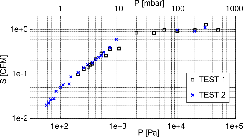
Leaks characterization
[NOTE FOR MYSELF]Now that we reviewed the baseline theory for the pumping-down process, we can do pretty much the same for characterizing leaks. First, we need to characterize the pump (in terms of pumping speed vs pressure for example - see previous section). We can do it by plugging directly the pump to a baratron, so that we minimize all other leaks, and go down to the minimum pressure attainable. Then, we can write a balance for the system, where in addition to a term MdotOut we have MdotIn due to the leaks. The point is, we can probably say that MdotIn is a constant, because it likely depends on the pressure difference, which means that it almost exclusively depends on the outer pressure (Patm >> Pvessel). The system is something like dn/dt = A - nS/V, with A constant. If we are lazy, we can integrate it numerically.
Future attempts
So, now that I have a rough system working, the next steps are:- Performing some leak detection to get down to some Pa, or below if possible;
- Building some feedthrough with spark plugs;
- Playing with some plasma;
- Moving to a better reservoir (stainless, not mild steel, nice and clean), see below;
- Implementing a diffusion or turbomolecular pump;
- Building a butterfly valve a (fixed one, that can be set only manually by opening the chamber shouldn't be too hard).
Cheers,
Stefano