Controlling a 4-wire fan with 555 PWM circuit
Cremona, August 2019.
This page is in the "junk" directory! Make sure you check some better material as well, on
the main page
:-)
Hello everyone!
I recently had the need to control the RPMs of a 4-wire fan (like these used in PC cooling), so here is a simple schematic that does it.
It is based on the 555 integrated circuit, connected in astable configuration.
In the following:
3 and 4-wire fans;
555 25 kHz PWM schematic;
How does it work.
Suggestions to improve the circuit - by Chris Fritz (fritzacoustics.com)
3 and 4-wire fans
In PC cooling you can find 2-wires, 3-wires and 4-wires fans.
In 99.9% of the cases these are brushless motors, with a control circuit embedded.
We don't care about 2-wire fans here.
3-wire fans have a +VCC wire (red), a GND wire (black) and the third one (yellow) is usually the tachometer signal, which is used
to read the RPMs of the fan.
If the fan does not rotate you get a nice error and the computer doesn't turn on.
You need to put a pull-up resistor of some kOhm and you monitor this pin, reading how many pulses you get in a second
(some fans will give one pulse per revolution, others two pulses).
That said, the 4-wire fan is pretty similar to the 3-wire, but has an additional wire for controlling the RPMs.
If you leave it open or you connect it to the +VCC, the fan will turn at its maximum (easy).
If you connect it to the GND, the fan will rotate at super slow speed.
Anything in the middle can be controlled by sending a PWM signal to this pin.
The signal must be at a frequency of 25 kHz (for some fans this may vary), and the duty cycle will determine the fan speed.
A common color code for 3-wire and 4-wire fans is reported below.
Control circuit
So, what we need is to create a circuit that oscillates at 25 kHz (I found in some datasheet that 21 to 28 kHz are OK).
There are a number of options, but probably the simplest one consists in a simple 555 oscillator in astable configuration.
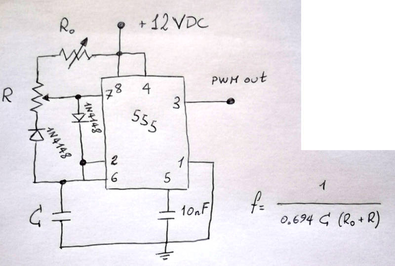
The schematic is shown in the next picture, and more explanation is given later on in this page.
Finally, at the end of this page, you'll find some notes about the drawbacks of this configurations and some suggestions for improving the circuit.
Values for R, R0 and C are given in a moment. The diodes are 1N4148.
An explanation of the circuit will be given also below.
Anyway, the idea is that by turning the potentiometer R, one can change the duty cycle, but the overall frequency does not
change.
This is because what is gained by the ON time is lost by the OFF time, and the total period of the signal is constant.
The resistor R0 is used to tune the frequency (components have a certain deviation from the ideal values).
For the values (see the picture below), you can chose them as to have a target of 25 kHz.
CASE 1: I had available a 10k trimmer (potentiometer, for "R"), a couple of 10nF capacitors (connected in series, they give C = 5 nF)
and a 4.7k trimmer for "R0".
I used these and it works just fine.
Note that the resistor R0 has the side effect of limiting the MINIMUM duty cycle attainable.
This is because during the charge phase, even if you set R as to give a 0% duty cycle, the resistor R0 will increase the
charge-up time.
In my case, I don't bother removing it, as the fan has a minimum value for the RPMs anyway, and I prefer having a way of
fixing the frequency, rather than none.
The duty cycle will go between roughly 15% and 100%.
CASE 2: another option is R = 4.7k trimmer, C = 12nF and no variable resistor R0.
This should give a frequency of 25 kHz with a minimum value of around 0% for the duty cycle, but cannot be frequency-tuned.
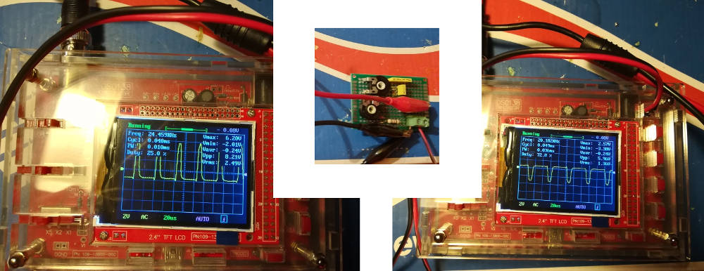
Here are a couple pics of a perforated board prototype (with some extra resistors, bypassed) and some tests on a cheap
20 euros oscilloscope.
The signal seems pretty smeared, so I checked it on the proper oscilloscope and it's much better:
Here is a video of the of the 555 regulating a 12V fan, with the control signal shown on the oscilloscope.
If the video doesn't work for you, click here to open it.
Circuit explanation
Let me explain here how the circuit works.
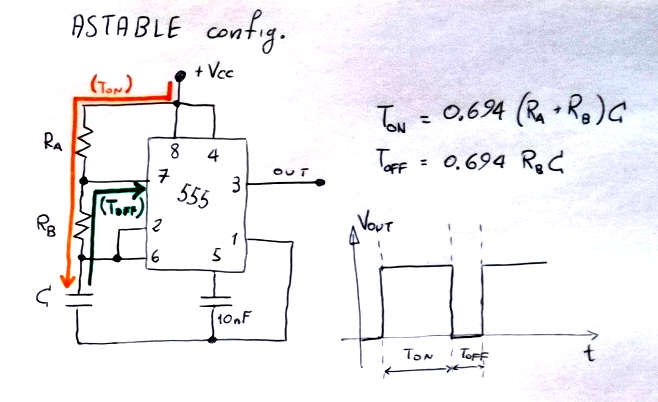
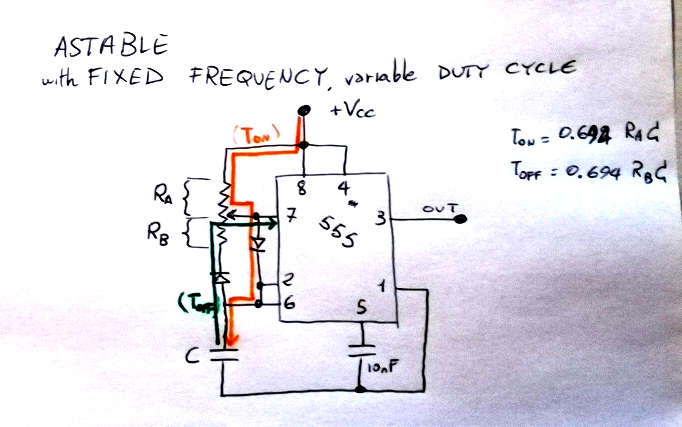
Let us start from the 555 in astable configuration (see next figure).
In the astable configuration, the 555 timer keeps oscillating between ON and OFF.
In the first half of the cycle, current will flow through the resistors Ra and Rb and will charge the
capacitor C. This is shown in organge in the figure.
The time for which the signal will be ON is around: Ton = 0.694*(Ra+Rb)*C.
After that, the discharge phase starts: current flows back to pin 7 (discharge pin) through the resistor
Rb (dark-green path in the figure).
So, the time for which the signal will be OFF is around: Toff = 0.694*Rb*C.
Note that this configuration has a "ON-time" clearly bigger than the "OFF-time", so the duty cycle is
always higher than 50%.
This is not good for our purpose.
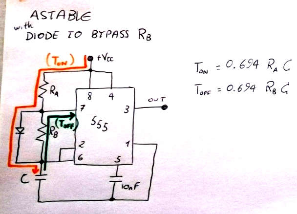
We can circumvent this problem by introducing a small diode in the circuit.
The diode will act as follows:
during the charge-up of the capacitor, the diode will by-pass the resistor Rb, such that the charge-up
time is Ton = 0.694*Ra*C.
During the discharge phase, current will flow as before through the resistor Rb, giving Roff = 0.694*Rb*C,
as before. See figure below:
Imagine to use variable resistors in place or Ra and Rb: you will be able to control the duty cycle at will.
However, if we change Ra and Rb individually, the period of the oscillation (T = Ton + Toff) may change,
meaning that the PWM frequency is not constant.
To do that, we can use a potentiometer.
The potentiometer (trimmer) has two ends and one middle connection.
Imagine it as the two resistors Ra and Rb connected together at the middle connection.
This will ensure that the total resistance Ra + Rb will be constant (thus preserving the oscillation
period and therefore the frequency), and will allow to change the duty cycle from 0 to 100% by turning one
only potentiometer.
Of course, we will need to use the diode trick as before.
This time, I inserted an additional diode. I'm not 100% sure if it's really needed or not, but most people
seem to use it. If you know why, please let me know.
See image below.
You'll want to watch out for the power dissipation in the variable resistor when set to a minimum pulse high-time. In this case, the capacitor will charge quickly thru Ra, which causes the discharge pin (7) to activate.
While this will slowly discharge the capacitor thru Rb, it also sources current out of the discharge pin, thru the small Ra to +Vcc.
If Ra value is too small, then I think the current flowing will be too great even for a high-power potentiometer, and might also be more current than the discharge pin is rated to source.
For my purpose, I just added a 1k 1/4w resistor between +12v and Ra, so the max current is 12mA, and ~.14W and it seems to be working so far.
I could see this not being a problem if the trimmer in your Case 1 circuit is never set to below ~1k.
I could also see possibly inverting the 555 output, then you could run it with a large Ra value.
I'm presuming that anyone building this would prefer more flexibility on the low-fan-speed end of the spectrum.