vacuum-diaries
THE VACUUM DIARIES
- or -

Rough and dirty vacuum testing: my path towards high vacuum


Cremona, 2018-ongoing...
Back to the VACUUM DIARIES page;
Or.. back to the home page.

Mass Flow Controller


Hi all,
in this page we'll see some Mass Flow Controllers (MFC), that allow us to inject gas into the chamber. I've bought for very cheap on ebay a SEC-7330 (by OSTEC, maximum 1 standard liter per minute of O2) and a Celerity 7300 (maximum, 30 sccm of He).

As most MFCs, these are analog units: you control the mass flow by applying a voltage to the INPUT pin (also called Setpoint), usually from 0 to 5 V, and this tells to the MFC the percent of full scale mass flow rate. The MFC reads this input signal and tries to open a valve accordingly. Also, they have some internal sensors for reading the actual mass flow rate: this indication is used by the MFC itself to self-adjust, and is also given to the user in the OUTPUT pin, that also goes from 0 to 5 V. Note that the Setpoint and the output do not necessarily coincide: you can ask so much mass flow to your controller, but it will only be able to let go a certain amount.
Usually, the MFCs are powered with -15,0,+15 V. In the following, I'll show a simple schematic for controlling them, and then an arduino circuit for reading the values through the USB (serial) port.

SEC-7330

The SEC-7330 gives a rather large mass flow rate of 1 slm (standard liter per minute) of molecular oxygen. This can be converted to other gases by using the conversion tables in the manual. In case you wonder, I'm using it for feeding a JxB plasma accelerator. Here's a picture of the MFC (Right-click to enlarge). Its electrical connections are printed on the back, and it uses a standard RS232 connector.

OSTEC SEC-7330

The circuit is simply a voltage divider with a 10k trimmer. The 20k resistor takes 2/3 of the applied 15V, that is 10V. Therefore, the 10k trimmer has 5V at its ends. By turning the knob, the voltage going to the input (IN) pin of the MFC ranges from 0 to 5V. In the figure, you'll see a LM78whatever voltage regulator, but it is in no way necessary for your circuit, and a simple voltage divider configuration should do the job. Note that some MFC models also offer a "5V reference output" pin, for making things even simpler!

As you can see, my schematic doesn't include an output voltage meter. It's trivial to add one though.

The fitting is a Swagelok of some kind. I didn't have any laying around, so I just used plenty of teflon tape, a transparent crystal tube, and a custom made reduction to reach the final tube size.

Celerity 7300 MFC

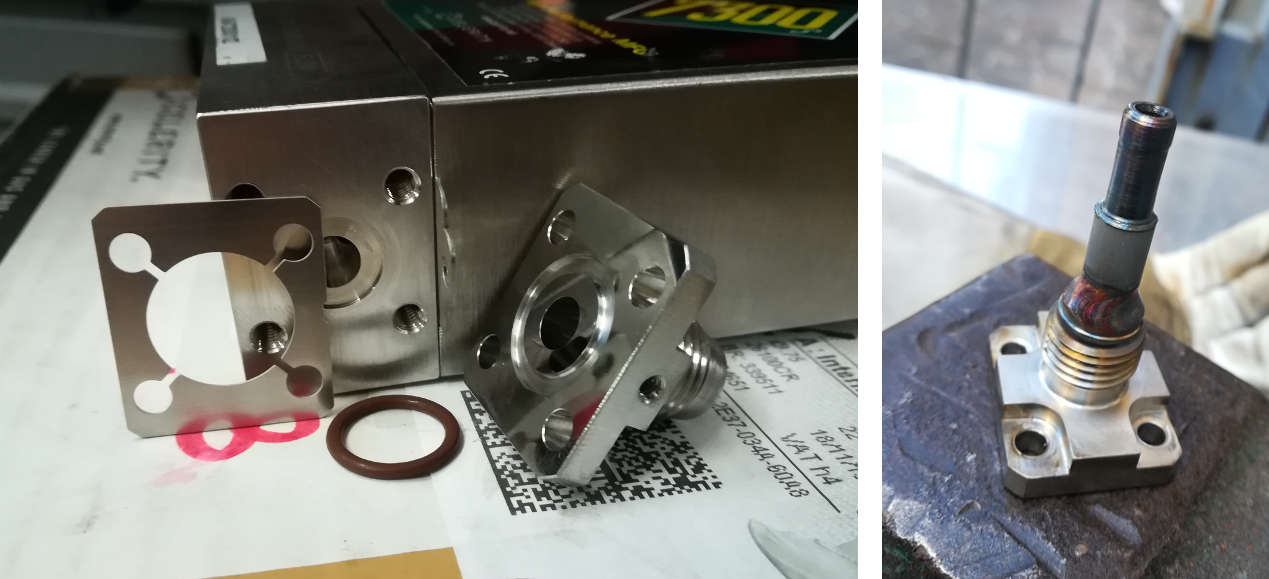
The second MFC that we review is the Celerity 7300. Here's a closeup view, with the unit opened.

Vacuum system and mass flow controller

As for the previous MFC, the interface is analogic. The input and output ends have a swagelok thread, which again is not so convenient for cheap tests, so I welded a simpler pipe connection on it. Of course, remove the connectors from the MFC before welding, or you'll cook the sealings:

Welding the connector

Schematic

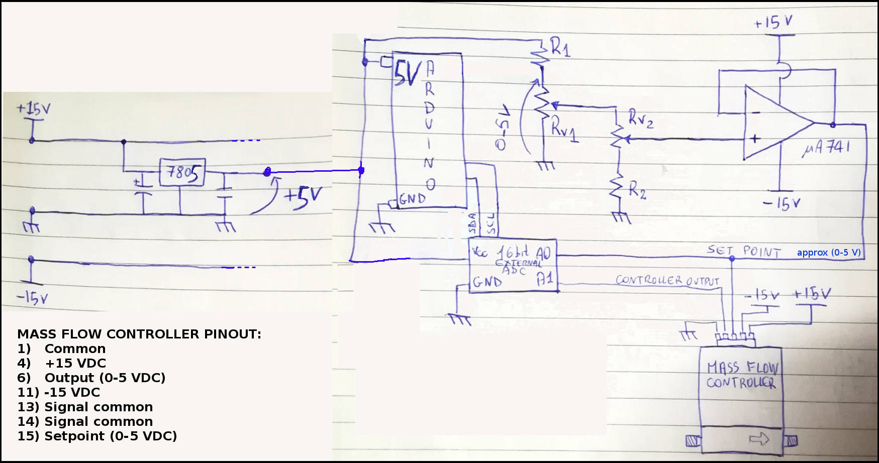
For controlling this MFC, you can use the very same schematic seen above. I wanted to have a reading of the output and the Setpoint on my computer, so I did something a bit more elaborate.
The schematic is quite rude (the drawing in the first place.. but also the electronics itself). I'm using Arduino to read the voltages, together with a 16 bits ADC (ADS1115). Then, I send both the setpoint and the output to the serial monitor and check them during the experiment.
As you can see, the schematic works on +15/0/-15V, and extract the 5V needed by Arduino using an LM7805. Also, the 5V are used to create the voltage divider to drive the Setpoint pin. You'll see two potentiometers in the schematic: these are used for the rough and fine tuning. The signal coming out of the voltage divider is in the range 0-5V, and is sent to a unit buffer (the operational amplifier) that allows to gain some current, in case the MFC requires a stronger input. I guess this is an overkill, though.

Arduino schematic for MFCController

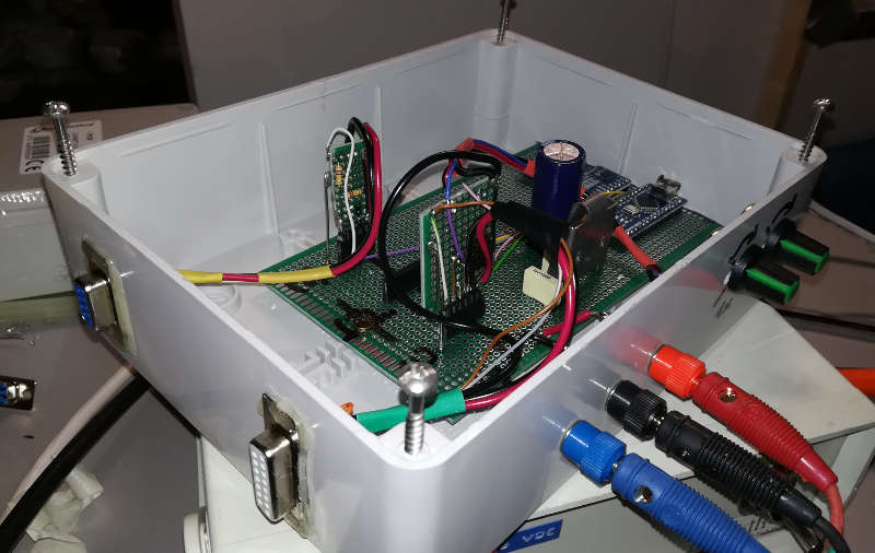
In the previous picture, you can see a little board that I assembled for convenience. It uses two AD1115 ADCs and is intended to read multiple sensors and pass everything via serial cable to the computer. Here's the Arduino script that I'm using:

#include <Wire.h>
#include <Adafruit_ADS1015.h>

// ADS1115 addresses: (GND - 0x48) (SDA 0x4A)
Adafruit_ADS1115 ads1(0x48);  /* Use this for the 16-bit version */
Adafruit_ADS1115 ads2(0x4A);  /* Use this for the 16-bit version */

void setup(void)
{
  // Serial monitor
  Serial.begin(9600);
  Serial.println("Hello!");

  ads1.setGain(GAIN_ONE);        // 1x gain   +/- 4.096V  1 bit = 2mV      0.125mV
  ads2.setGain(GAIN_ONE);        // 1x gain   +/- 4.096V  1 bit = 2mV      0.125mV
  ads1.begin();
  ads2.begin();
}

void loop(void)
{
  // ADC reading 
  int16_t adc1_0, adc1_1, adc1_2, adc1_3; // FIRST ADC
  int16_t adc2_0, adc2_1, adc2_2, adc2_3; // SECOND ADC

  // Read from first ADC
  adc1_0 = ads1.readADC_SingleEnded(0);
  adc1_1 = ads1.readADC_SingleEnded(1);
  adc1_2 = ads1.readADC_SingleEnded(2);
  adc1_3 = ads1.readADC_SingleEnded(3);

  // Read from second ADC
  adc2_0 = ads2.readADC_SingleEnded(0);
  adc2_1 = ads2.readADC_SingleEnded(1);
  adc2_2 = ads2.readADC_SingleEnded(2);
  adc2_3 = ads2.readADC_SingleEnded(3);


  // Average values in time
  double avg_bits_1_0 = 0; // Setpoint Mass flow controller
  double avg_bits_1_1 = 0; // Output Mass flow controller

  double avg_bits_2_0 = 0; // Output 10 Torr pressure gauge
  
  int Navg = 250;
  
  for(int ii = 0; ii < Navg; ++ii)
  {
    avg_bits_1_0 += (double)(adc1_0)/Navg;
    avg_bits_1_1 += (double)(adc1_1)/Navg;

    avg_bits_2_0 += (double)(adc2_0)/Navg;
  }

  // Convert to voltages
  double Vsetpoint_mV = avg_bits_1_0*0.125; // Setpoint voltage Mass flow controller
  double Voutput_mV   = avg_bits_1_1*0.125; // Output voltage Mass flow controller

  double Voutput_mV_Pressure = avg_bits_2_0*0.125; // Output voltage pressure gauge (divided by two)
  double P_Torr = Voutput_mV_Pressure/1000/5*10;
  
  Serial.print("\n");
  Serial.print("Setpoint - He: "); Serial.print(Vsetpoint_mV); Serial.print(" mV  "); Serial.print(Vsetpoint_mV/1000*30/5); Serial.print(" sccm\n"); // "30" -> 30sccm FS mass flow controller
  Serial.print("Output   - He: "); Serial.print(Voutput_mV);   Serial.print(" mV  "); Serial.print(Voutput_mV/1000*30/5);   Serial.print(" sccm\n"); // "30" -> 30sccm FS mass flow controller

  Serial.print("\n");
  Serial.print("P: "); Serial.print(Voutput_mV_Pressure); Serial.print(" mV  "); Serial.print(P_Torr); Serial.print(" Torr   =   "); Serial.print(P_Torr*133); Serial.print(" Pa\n");

  delay(1000);
}
Testing

In this section, I'll test the Celerity MFC.

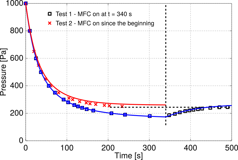
So, how do we know if the guy is working? First off, the manual says that in order to work properly, it must warm up for some time (like 40 minutes if I'm not mistaken). That said, there is a simple way: assuming there are no leaks in the system (or at least, leaks are much smaller than the MFC mass flow rate), one can infer the mass flow rate from the equilibrium pressure. What you need to do is writing an equilibrium between the injected mass and the gas mass pumped away by the vacuum pump. I'll explain this below. For now, check out the following plot:

Pressure experiments and simulation

I did two experiments:
  1. TEST 1 (black squares) - First, I keep the mass flow rate at the very minimum (kind of switched off) and pump down the chamber. While pumping down, I measure the pressure in time and from such data I can compute the pumping speed of the system (see this page); At time t = 340 seconds (roughly), I switch on the MFC, and you can see the pressure starts to rise and eventually levels off.
  2. TEST 2 (red crosses) - Then, I vent the chamber completely and I start a new test from scratch. This time, I keep the MFC on all time since the beginning. Again, I measure the pressure in time and plot it. From atmospheric conditions, the pressure drops slowlier this time, since some mass is being injected in the meanwhile.
The symbols in the figure represent the data from TEST 1 and TEST 2.
From TEST 1, I compute the pumping speed of my pump+pipes assembly, as a function of pressure: S(P). This is enough for estimating the mass flow rate. It is sufficient to write an equilibrium in mass fluxes. Notive that MASS is what is being conserved, regardless of the system pressure (and not volume or density or anything, that change with pressure). You write "mdotIN = mdotOUT", where "mdotOUT=mN2*nVessel*Spump=mN2*P*Spump/(kB*T)". Since the final pressure is about 247.5 Pa, we have "mdotOUT=1.55e-7 kg/s = 7.46 sccm" of air. This is equivalent to 10.8 sccm of He (considering a conversion factor of 1.45). I'm considering T = 283 K in the calculations, that is kind of fair. Not exactly what we expected, but close! So, we know the system is working.

This is deviating by some 25% from the expected result of 14.5 sccm of He, which is probably due to several factors:
  1. my pressure gauge is poorly calibrated;
  2. the pumping speed estimation is also poor and should be revisited;
  3. I didn't let the MFC warm up (as the manual suggests), so my results could be off for this reason as well;
  4. I'm not correcting my calculations for the real ambient temperature.

A check: numerical simulation

In the previous figure there are also some lines, superimposed. These are obtained from numerical integration of the following mass balance: dP/dt = mdot*kB*T/(m*Vvessel) - P*S(P)/Vvessel, where "mdot" is the mass flow rate, "m" the gas molecular mass, "kB=1.38e-23 J/K" the Boltzmann constant, "T" the temperature in Kelvin, S(P) the pumping speed (function of the pressure) measured in TEST 1 and Vvessel the vessel volume. At this link you can find an Octave/Matlab script that plots the data and integrates such equation.

For TEST 1, the "mdot" inlet mass flux is set to zero in the beginning, and is switched on only at t = 340 s.

I'll do some more testing and better calculations time permitting, to make sure the MFC is accurate. That's it for now!

Cheers,
Stefano

Where to go now?
Back to the VACUUM DIARIES page;
Or.. back to the home page.