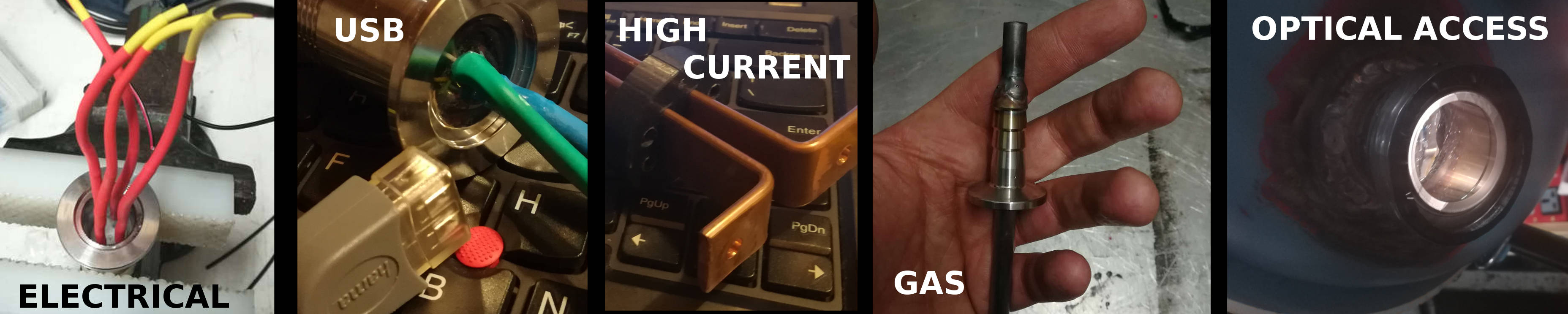
Here's a "graphical abstract" of what you'll find in this page:
Feedthroughs are an often pointlessly expensive part of the vacuum equipment.
If you are short on budget and you don't need ultra-high vacuum, you can totally build your owns.
In this page you can find some notes about my failed and successful attempts of building feedthroughs using standard KF-X connectors.
The goal is building everything bottom-up, and avoiding complex methods such as glass-metal junctions and the like.
These feedthroughs were testes up to a bit below 1 Pascal (7.5 mTorr) and appeared to work faultlessly.
Here are two lessons learned:
Don't use hot glue for holding the vacuum.
Don't use polyester resin either, do use epoxy instead.
I didn't notice any difference by degassing the epoxy into vacuum before curing. Maybe it will at lower pressures, maybe.
Electrical feedthrough - tests 0 and 1 - big failures
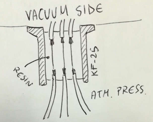
For the first tests, the idea was using some resin to glue the wires inside a KF-25 ISO connector.
To prevent air leaking through the wires rubber sheath, I cut the wires and tin soldered them to some nickel wires.
The resin should glue to the nickel wires and prevent air from leaking in.
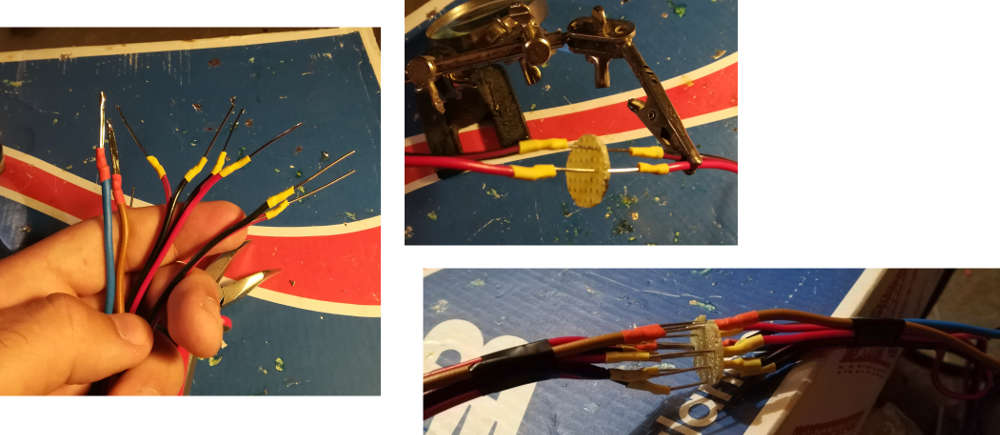
Then put some heat-shrinking sheath around to prevent contacts during the building phase, and soldered also the other side of the wires.
To keep the wires separated, I used a perforated board, where I removed the circular copper base plates.
The pictures are quite self-explainatory.
So, at this point I put this into the KF-25 flange, clogged the outer side with electrical PVC black tape and prepared the polyester resin.
"Resin is viscous enough and it will get hard quite fast, so it won't flow through the small holes between the tape."
No, it was a failure, all the resin flowed through the hole down on the ground.
Lesson learned: you need to clog one side very well (this is even more true for epoxy resin, as it polymerizes much more slowly).
Ok, so let's do it again, from scratch, and this time let's use some hot
glue to block the inner side before pouring the resin.
Not sure why I didn't block the outer side, as this would be much neater from the vacuum perspective...
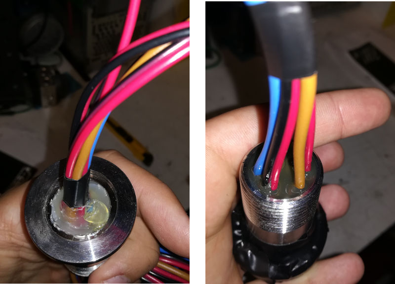
Anyway, it kind of worked (although some resin somehow found its way through the hot glue (did it corrode it? did it melt it getting a bit warm?).
Anyway, looked good, see images below.
So, the inner side was hot glued, the outer side was a nice block of resin blocking the wires in place (and nichel wires as well).
Did it work?
No.
Some how it wasn't holding the vacuum.
Actually, I started pumping down and the pressure went down straight to 600 Pa, then 550 Pa, then it stalled and it started rising again.
What?!
Maybe hot glue is degassing or small bubbles are exploding in the vacuum? Maybe some air trapped inside the wires is leaking all of a sudden?
I tried to place the connector alone inside the vacuum chamber, closing all apertures and pumped down, but no, it was not degassing.
So, to make it short, probably everything was leaking there.
One last test, let's connect it, let's create some vacuum, and while the pump is sucking, let's put extra hot glue all around the exit.
I actually ended up putting much more than in the picture.
Is it working?
Yeeeees!!
It worked well enough to go down to 250 Pa so that I could test some plasmas, but then all of a sudden it stopped working. Also, something nasty happened inside, because the connectors probably shorted while making some discharges.
So, now this setup leaks like hell (I can't get below 1 mbar) and wires are shorted.
FAILURE! Let's move to a new setup.
Lessons learned:
Polyester resin gets hard fast and is very rigid. NOT SUITABLE.
Beware hot glue, it's not that good for vacuum (as you may have guessed since the beginning hahah).
Electrical feedthrough - tests 2 and 3 - success
Ok so, let's do it again, this time with epoxy resin.
Below a bad picture of the resin I used, the brand is Mold Art or something like that.
It's a bi-component, mixing ratios are 100-60 in mass (10 g of component A, 6 g of component B).
Apparently the component A is the base one, while there are a number of variants for component B (called C, D, etc), which give different properties to the resin.
After mixing the resin, I decided to degas it by putting it in the vacuum.
Mainly, I was curious to see what goes on, but for sure this should help the performance.
So, after putting it in the vacuum, I went down to 10 mbar or maybe below.
At the beginning some bubbles on the surface will pop very gently.
After a while, bubbles will start to create all inside the volume, even if they were too small to be seen or even if apparently there was none.
The bubbles will all come up and start popping, creating a foam.
After a while the foam will be disappeared, and you will be good to go.
The image below is taken at the end, when most of the foam was gone and the resin was degased.
The first test (test #2) was to see if this epoxy would hold well the vacuum.
So I took 4 straight nichel wires, put them inside the KF-25 flange, keeping them in place on the outer end, by using again hot glue.
I know I should use something else, but I only had this at hand at the moment.
Moreover, the test is mainly to see if this holds the pressure.
So, first of all, surface preparation: I rubbed with acetone the nickel wires and the inner wall of the chamber.
Then I poured epoxy, this time on the inner side of the KF-16 connector.
Results: some epoxy managed to pass through the hot glue plug, but only a few drops, although it stayed liquid for a number of hours.
Watch out: even when it seems that it got plastic, don't displace the guy, but keep it well vertical in position.
It will still flow as a liquid.
Ok, when dry, after about 1 day I plugged it to the chamber and tried the vacuum.
It was holding it really well.
So, I soldered some wires to the inside of the nickel feed-through wires, and put a lot of heat-shrinking tubing around it, to prevent sparks (see pictures below).
Then poured additional resin.
Some air is probably trapped inside the heat shrinking tube, but this should either evacuate easily, or anyway shouldn't give too much issue.
The important thing is that the interior is well isolated from the outer side by the nickel wires embedded in epoxy.
Finally, while building the previous one, I also tried out a slightly different version, by including a teflon spacer that should help to keep everything in place.
So, I machined a teflon piece (see image below), and welded nichel wires through it, to the connectors.
Then, clogged the outer side with hot glue to prevent epoxy from flowing out from small holes, and finally poured the resin.
I tested these feedthroughs using a flyback transformer driven at roughly 50 kV, and a MOT at 2 kV and some more amps.
All was good and I didn't notice any issue.
A continuous long-time test was not run, though.
USB feedthrough
At a certain point, I didn't have optical access to the chamber, so I tought of putting a webcam inside the vacuum chamber, and then connect the four USB cables through
the electrical feedthroughs.
To my surprise the webcam wasn't working.
The cable length was pretty much identical, and trying to dump some info with the "dmsg" command on linux didn't help
(at least, I couldn't really understand what was going on... and I don't remember the result anyway).
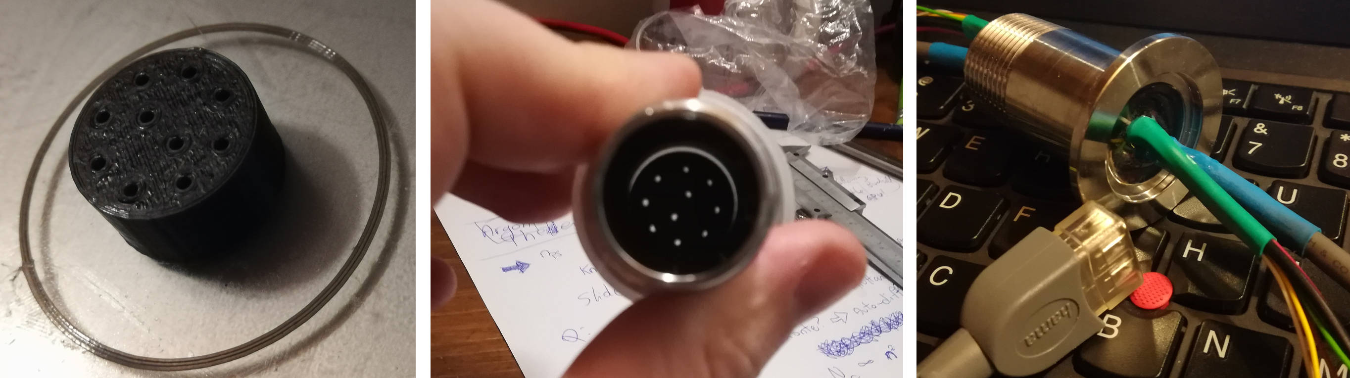
So, what I did is just creating a new feedthrough, still using a spare KF25, but this time I placed the contacts pretty close to each other.
To do this a bit more accurately, I've printed a small spacer using the 3D printer.
It is not fitting perfectly the KF25, and this would have leaked some epoxy while curing, so I've used some electrical tape to increase the diameter,
and filled the holes with a super tiny little amount of hot glue.
Not much, I promise.
For the rest, I've kept the naked wire connectors (embedded in the resin) much shorter than for the previous feedthroughs.
The result was warking straight out, and the quality of the webcam appeared to be the same as for a direct connection.
I'm also using a USB extender cable.
Here are a couple of pictures.
IMPORTANT NOTE: webcams appear to be quite susceptible to electromagnetic interference.
For example, every time that I try to use the webcam and use the MOT transformer at the same time to produce some discharges, the webcam gets crazy and crashes.
This happened with two different models (both cheap).
You may have some luck though... just alerting you here.
The message here is: putting a webcam in the vacuum may be a bad idea. Putting it near a high voltage plasma may be an even worse idea.
If you want to do this nonetheless, make sure that the naked contacts inside your feedthrough are very compact.
High current feedthrough
If you need to have a reasonable amount of current (for example, for some large thermionic emission cathodes), nickel wires alone won't do.
Here's a version of the feedthrough that uses two copper bars instead, and a KF40 flange to provide some more space.
Each bar is 3mm thick and 20mm wide.
This version is fundamentally alike to the vanilla electrical feedthrough.
First, the copper bars are shaped.
As obvious as it may sound, keep in mind that the shaped bars need to pass through your opening, in the vacuum chamber!
Then, I've 3D printed a support to keep them in place inside the KF-40 flange (and to keep epoxy in place while curing).
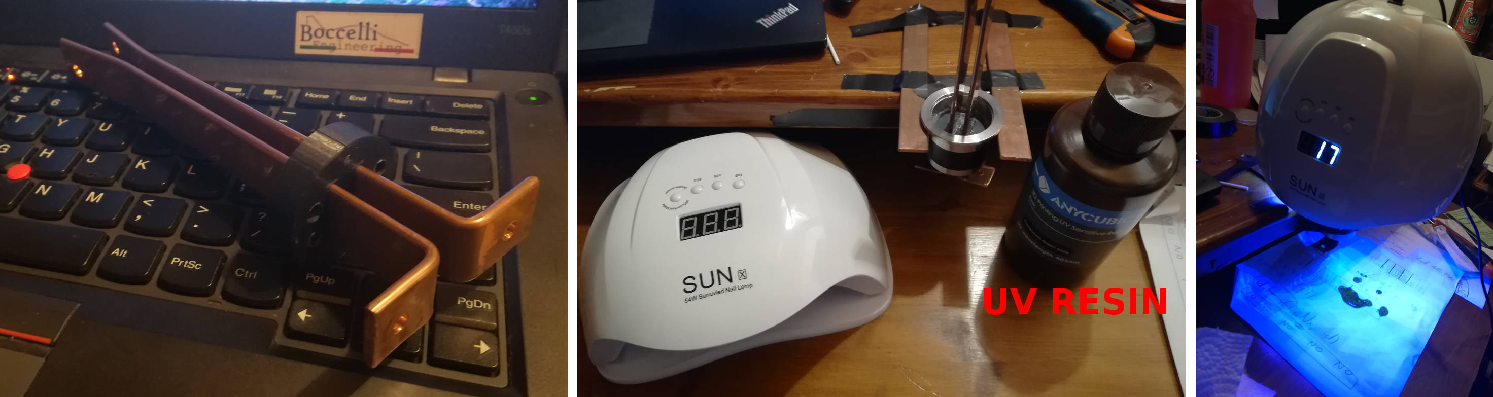
Once in place, the support and the copper bars were hot-glued together (using the least possible hot glue, and only to fill the holes).
Actually, I had some 3D printing UV resin laying around, so before pouring the epoxy, I thought of pouring some UV resin, and curing it quickly with
an UV nails curing lamp.
This turned out to be a good idea, since apparently I had left a few spots open, and some (slowly curing) epoxy would have poured out.
Important: this step is done only for plugging any possible hole, and to prevent . I have no clue on how well the UV resin would hold the vacuum,
so only create a small layer of it, and leave plenty of space for subsequenty layers of epoxy.
Important: as always, clean well the surfaces, for having a good adhesion! This is especially important for copper, that tends to oxidise easily.
Gas feedthrough
A gas feedthrough can be used to fill the chamber with some gas and try out discharges in a different atmosphere than pure air, or can be used to feed some devices.
For electric propulsion for example, you need to feed some xenon/argon/krypton whatever to the device, then ionize and accelerate it out of the thruster.
So, I basically need a hose going into the chamber.
First Test - FAIL!
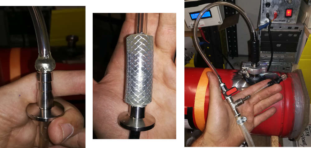
First, I tried to use a KF-16 hose connector (see picture below), and fitted a small crystal tubing, that was fitting almos exactly the hole, passing through it.
The crystal tube goes inside the chamber for about 15 cm.
So, since the hole is small anyway, I guessed hot glue can be just fine (not quite, actually).
I connected the KF-16 flange to the vacuum system, started the vacuum and put inside the crystal tube.
After clogging the tube, air would leak in from the gap between the tubing and the KF-16 connector.
So, I warmed up a bit the connector with a torch, and started putting hot fglue on the sides, which would get fantastically sucked in.
Don't heat too much or the glue gets too liquid and flows 100% inside.
Then, to add some structural strength, I covered everything with a larger hose (gardening-like), and poured abundant hot glue on both sides.
In 2019 I wrote:
So far, it seems holding the vacuum pretty well.
I may update the page in case I have some problems in the future.
So here we go... September 2020:
Probably the feedthrough didn't pass a nice winter.
After trying it, not it was not able to get below some kPa.
Pretty disappointing.
I gave hot glue many chances, but now I'm very sure: hot glue sucks for vacuum applications.
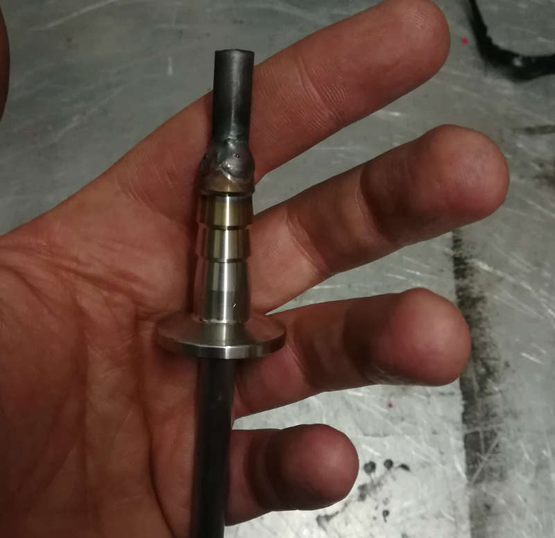
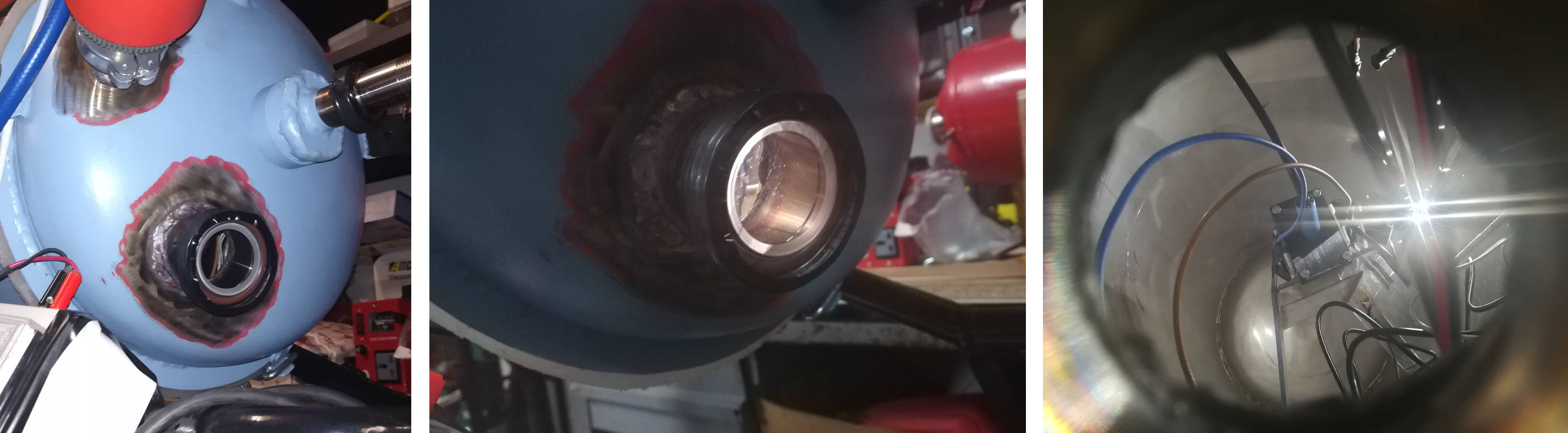
Welded version
I have a TIG welding machine handy, and I can weld some pretty small thicknesses, so I decided to just weld a small piece
of tiny steel tubing to the KF-16 connector.
Here's it.
I really wonder why I didn't do that before...
Optical access
Needless to say, having an optical access into the vacuum chamber is a must.
A small optical access may be enough, if you can accept to stick close to it for observing, or if you just want to have a small camera watching into the
chamber.
Of course, a small port implies less stress on the (brittle) transparent material, that is a big plus.
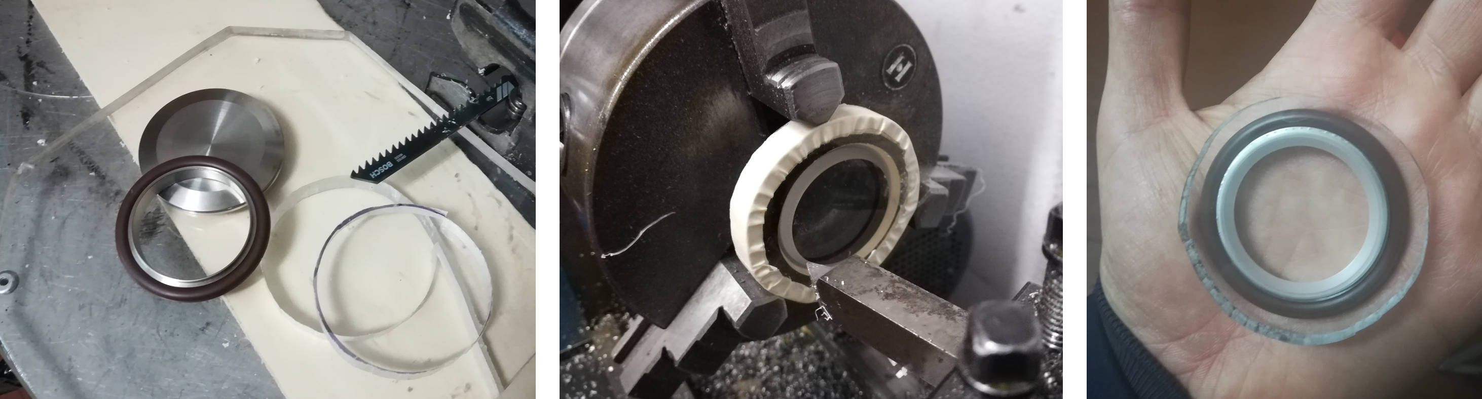
I decided to build an optical access to be mounted on a KF40 flange that I had previously welded to the vacuum chamber.
The gasket for these flanges is made by an o-ring that is supported by a small aluminium support, with two small lips to keep it centered.
All you have to do is to cut a round piece of thick acrylic (plexiglass, polycarbonate, or whatever) - in my case it is 10 mm thick - and to carve a
slot for the lips of the support.
Here are a couple of pictures.
The slot for placing the gasket is obtained on the lathe.
You don't need the external border to be necessarily extra regular, the important is just that it covers properly the sealing.
Of course, a standard KF-40 clamp won't fit the optical access anymore.
This is not a problem though: you can use some electrical tape to keep in place, and once you create the vacuum, the external pressure
will keep the optical access in place for you.
Here is the completed setup: